(24/09/2023)
3D Print your own:
https://github.com/ThatMechatronicNerd/3DPrintable_GA_Flight_Simulator_Whiskey_Compass.git
(04.08.2023)
First little mechatronic project up here, more to follow with the history of this project, the design philosophy and the mix of tech involved to make it happen…
(04.08.2023)
Some background: years ago (around 2010) I designed and prototyped a simulated whiskey compass for FNPT devices (Flight Simulators)
Project: Flight Simulator “Whiskey” Compass
Objective: Design and Produce a simulated “Whiskey Compass” for procedural Flight Simulator Use
Skills Involved: PCB Design, Embedded Firmware, Hardware
Design Philosophy:
Enclosure:
The intention was to design an enclosure that was machinable, at the time I had access to two Subtractive Rapid prototype Roland MDX Machines. The enclosure was made out of parts designed to press together much like a high end injection moulded aeroplane model kit.
The urethane material (chemical wood) finished beautifully with Duco paint so in terms of aesthetics I could expect a fairly nice finish.
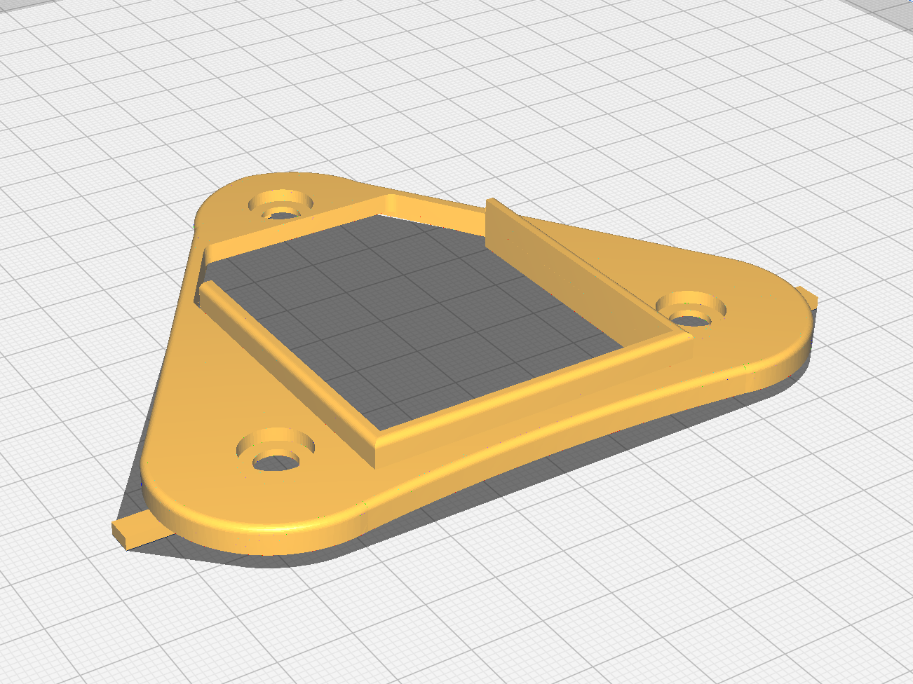
Here you can see the one half of the body and the base plate.
Notice the bridges (to hold the part in the block of material the part is machined out of) on the part for the Subtractive Rapid Prototyping (SRP) process. Those were then gently cut off and filed down.
Actuation:
The Compass Ribbon was to move on a stepper motor so a PIC MCU and Stepper driver IC with microstepping made a lot of sense for that.
The device had to feature ruggedised communications so RS485 was a good fit.
PCB:
From the required functionality in terms of actuation and homing of the stepper motor and the communication requirement the scope of the PCB became clearer.
So… scope of work + coffee + engineering time = solution
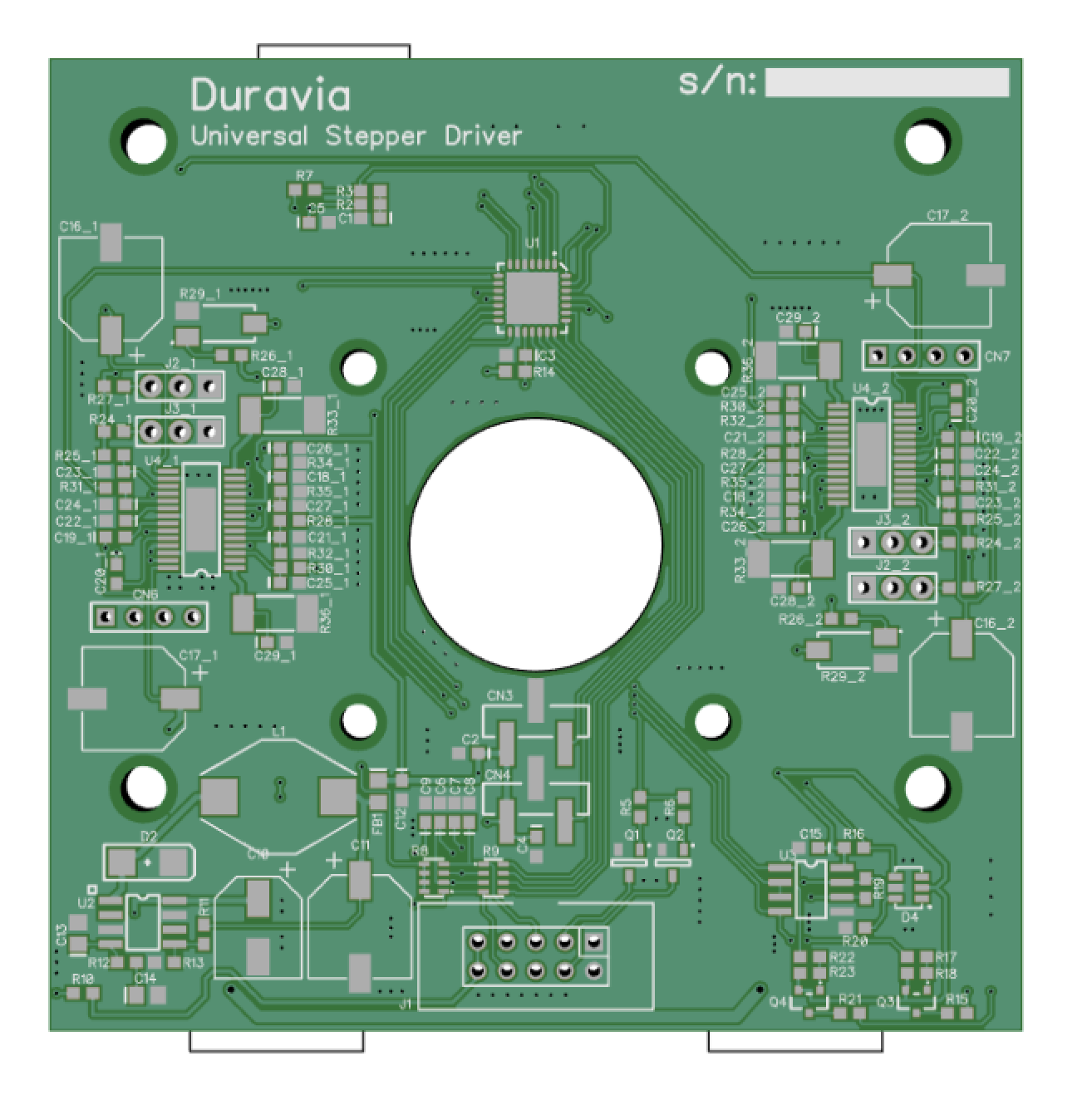
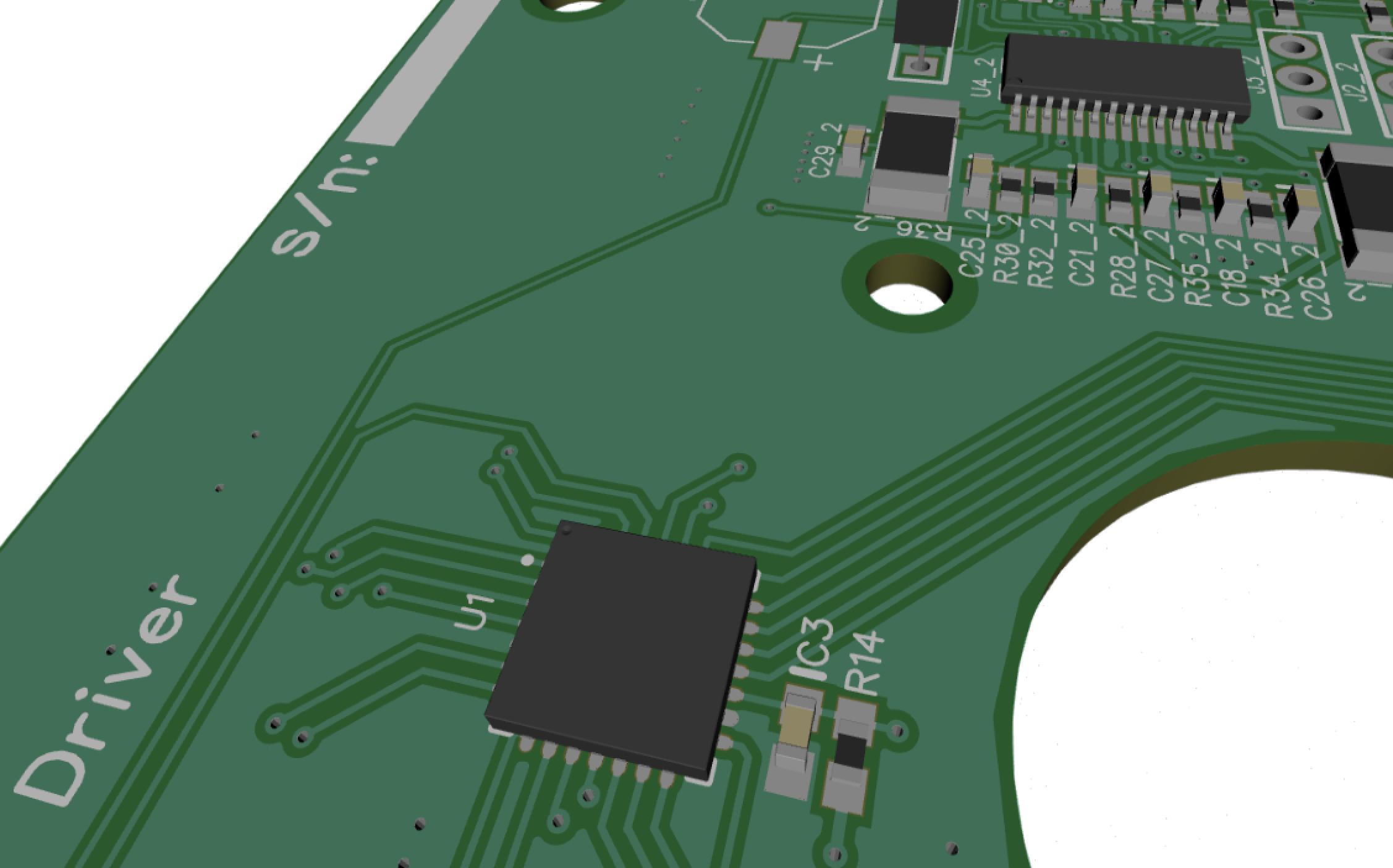
Some eye candy for those who enjoy some PCB simulation and visualisation before prototype production…
(13.08.2023)
Great success:
A PCB Design was completed and produced, the SMT components stuck on there with some care.
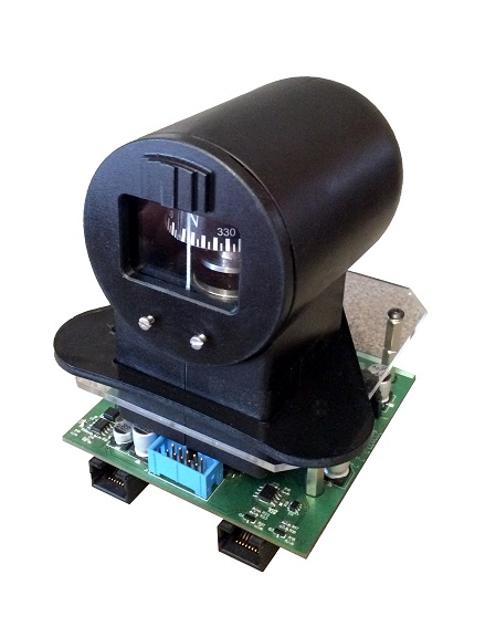
Some firmware for the PIC18F26K22 was written and an enclosure for the stepper motor, homing disc and optical home sensor was completed.
The end product as pictured at the start of the post.
So what would I do differently in 2023:
Well.. A whole lot.
1: 3D Printing:
For starters 3D printing some the mechanical bits could speed up the design cycle a whole lot. It is worth mentioning that 3D Printing has gone from “Fabbing” with M8 threaded rod driven XY Tables with modified glue guns as the extruder to a really great prototyping tech and batch production tool for professionals and “makers” alike. So in the spirit of that one would probably think “well lets 3D print out an exact unit from the machine files from the past”.
Well not so fast: shrinkage, wall thickness and a few other challenges would probably prevent that from being a bunch of great 3D printed parts.
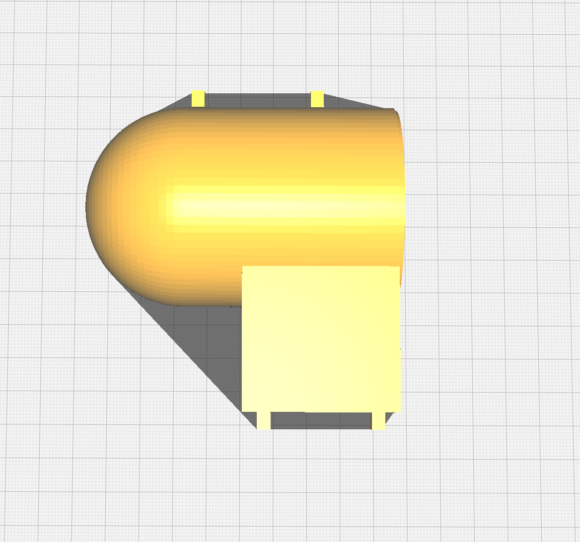
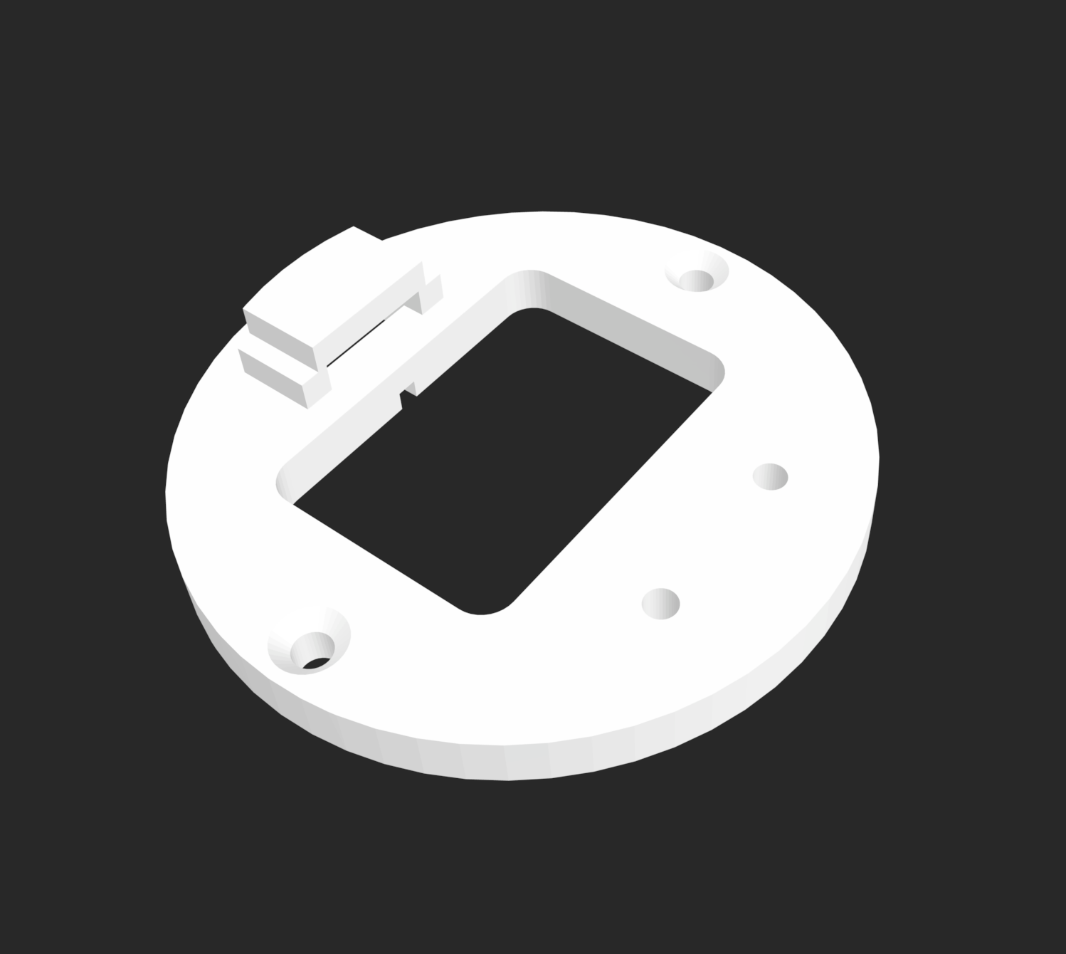
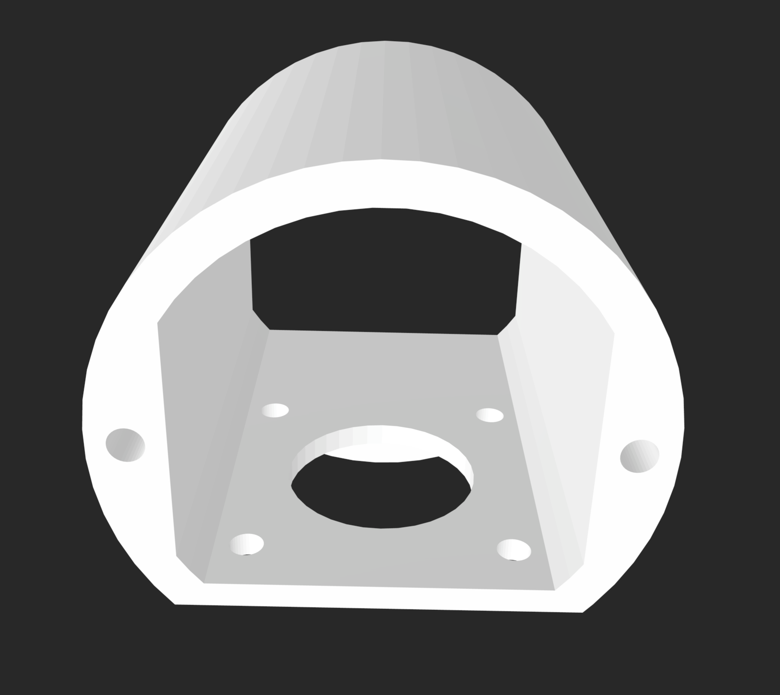
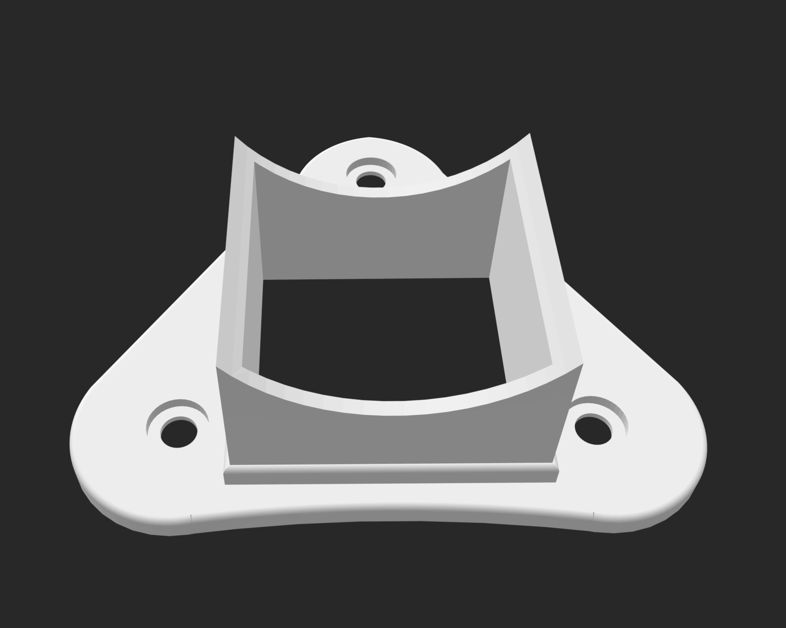
To make provision for this newer additive prototyping technology here are some screenshots of the updated 3D printable version:
Leave a Reply